Knowledgebase
Arduino Lesson 12 – Automatic Fan Control System
මෙහිදී අපි බලමු temperature sensor එකක් මගින් ලබා ගන්නා දත්ත අනුව මෝටර් එකක් හසුරවන්නේ කොහොමද කියලා. මේකට අපි යොදා ගන්නේ LM35 කියන temperature sensor එක. මෙහිදී අපි කිසිම මෝටර් control එකක් භාවිතා කරන්නේ නැහැ. ඒ පිලිබදව ඉදිරි පාඩමක් අරගෙන එන්න බලාබොරොත්තු වෙනවා. මෙහිදී අපි සිදු කරන්නේ මෝටර් එක ON/OFF කිරීම පමණයි. මෝටර් එකහි වේගය පාලනය කිරීම මෙහිදී සිදු කිරීමට හැකියාවක් නැහැ.
LM35 Temperature Sensor to an Arduino – Simple Thermometer
අවශ්යය උපාංග
[gap height=”25px”]
[ux_products style=”vertical” type=”row” columns=”2″ depth=”1″ depth_hover=”2″ show_quick_view=”0″ equalize_box=”true” ids=”423,4125,4134,4143,6277″ image_width=”42″ image_hover=”grayscale” text_pos=”middle” text_align=”left”]
උපාංග පිලිබද දැනුම
LM35 Temperature sensor
LM35 යනු අඩු වෝල්ටීයතාවයක් මගින් ක්රියා කරන නිවැරදි සෙන්ටිග්රේඩ් උෂ්ණත්වය සංවේදකයකි. එය සෙන්ටිග්රේඩ්(°C) උෂ්ණත්වයට රේඛීයව සමානුපාතික වන වෝල්ටීයතා සැපයුමක් සපයන චිපයක් වන අතර එය එය ආරඩුයිනෝ සමග පහසුවෙන් භාවිතා කළ හැකිය. මෙය නිර්මාණය කරනු ලබන්නේ Texas Instruments ආයතනය මගිනි
[row]
[col span__sm=”12″ align=”center”]
[ux_image id=”8278″ width=”7″]
[/col]
[/row]
සංවේදකය 4v සිට 30V දක්වා පරාසය තුළ බල සැපයුමක් භාවිතා කළ හැකිය. ක්රියාකාරී තත්වයේදී එය 60µA ආසන්න විදුලි බලයක් පරිබෝජනය කරයි.
සම්පූර්ණ විස්තරය පහත දැක්වේ :
| Power supply | 4V to 30V |
| Current draw | 60µA |
| Temperature range | −55°C to +155°C |
| Accuracy | ±0.5°C |
| Output scale factor | 10mV/°C |
| Output at 25°C | 250mV |
වැඩි විස්තර සදහා මෙහි datasheet එක බලන්න
LM35 සංවේදකයේ ඇති එකම අවාසිය නම් එයට සෘණ(negative) උෂ්ණත්වය මැනීම සඳහා සෘණ වෝල්ටීයතාවක් අවශ්ය වීමයි. එබැවින් ඔබ සෘණ උෂ්ණත්වය මැනීම සඳහා සංවේදකය භාවිතා කිරීමට සැලසුම් කරන්නේ නම්, ඔබ TMP36 උෂ්ණත්ව සංවේදකය භාවිතා කිරීම වඩාත් සුදුසු වේ. TMP36 යනු ඇනලොග් ආකාරයට දත්ත ලබා දෙන -40 °C සිට 125 °C දක්වා තරමක් නිවැරදි වන අතර සෘණ වෝල්ටීයතාව නොමැතිව සෘණ උෂ්ණත්ව මැනීමට හැකි වේ
LM35 සඳහා තවත් වඩා හොඳ විකල්පයක් වන්නේ DS18B20 ඩිජිටල් උෂ්ණ සංවේදකයක් භාවිතා කිරීමයි.
වැඩ කරන ආකාරය
LM35 උෂ්ණත්වය මැනීම සඳහා ඉතාමත් හොද කරමයකි. එය උෂ්ණත්වය වැඩි වන විට ඩයෝඩ්යට සම්බන්ධ ට්රාන්ස්සිටරයේ base සහ emitter පින් (forward voltage – Vbe) අතර වෝල්ටීයතා පහත වැටීම සිදු වේ. එමගින් මෙම වෝල්ටීයතා වෙනස හරියටම නිර්ණය කිරීමෙන්, උෂ්ණත්වයට සෘජුවම සමානුපාතික වන ඇනලොග් සිග්නල් ලබා ගැනීමට හැකිය.
ඉදිරි වෝල්ටීයතාව සහ උෂ්ණත්වය අතර මෙම රේඛීය සම්බන්ධතාවය ඩයෝඩ් සම්බන්ධ ට්රාන්සිස්ටර උෂ්ණත්ව මිනුම් උපාංග ලෙස භාවිතා කිරීමට හේතුවයි. වසර ගණනාවක් තිස්සේ මෙම තාක්ෂණයෙහි යම් වැඩිදියුණු කිරීම් වැඩිදියුණු කිරීම් සිදු කර ඇතත්, උෂ්ණත්වය මනින ආකාරය මෙයයි. මෙම තාක්ෂණය පිළිබඳ වැඩි විස්තර මෙහි සොයාගත හැකිය.
ශුභාරංචිය නම් මෙම සංකීර්ණ ගණනය කිරීම් LM35 තුළ සිදු කිරීමයි. එය උෂ්ණත්වයට රේඛීයව සමානුපාතික වන වෝල්ටීයතාවයක් ප්රතිනිර්මාණය කරයි.
ඉදිරි වෝල්ටීයතාව(forward voltage) සහ උෂ්ණත්වය අතර රේඛීය සම්බන්ධතාවය ඩයෝඩය සම්බන්ධ ට්රාන්ස්සිස්ටරය උෂ්ණත්ව මිනුම් උපාංගක් ලෙස භාවිතා කිරීම මෙයට හේතුවයි වසර ගණනාවක් තිස්සේ මෙම තාක්ෂණයෙහි යම් වැඩිදියුණු කිරීම් සිදු කර ඇතත්, තවමත් උෂ්ණත්වය මනින ආකාරය මෙයයි. මෙම තාක්ෂණය පිළිබඳ වැඩි විස්තර සදහා මෙය බලන්න here.
කෙසේවෙතත් මෙම සංකීර්ණ ගණනය කිරීම් LM35 තුළ පහසුවෙන් සිදු වේ. එය උෂ්ණත්වයට රේඛීයව සමානුපාතික වන වෝල්ටීයතාවයක් ප්රතිනිර්මාණය කරයි.
උෂ්ණත්වය මැනිය හැකි ආකාරය
LM35 සෙන්සරය භාවිතා කිරීම ඉතා පහසුයි. සංවේදකයේ පැතලි පැත්ත ඔබට මුහුණ දී ලෙස තබා ගත් විට වම්පස පින් එක (4V සිට 30V දක්වා) වෝල්ටීයතා සැපයුමකට සහ දකුණු පස පින් එක GND සමග සම්බන්ධ කරන්න. එවිට මැද පින් එක මඟින් °C වලට සෘජුවම සමානුපාතික (රේඛීය) ඇනලොග් වෝල්ටීයතාවයක් ලබා ගත හැකිය.ප්රතිදාන වෝල්ටීයතාවයේ සහ උෂ්ණත්වය අතර සම්බන්ධය පහත ආකාරයට පහසුවෙන් දැකිය හැකිය.
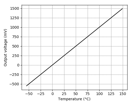
වෝල්ටීයතාව උෂ්ණත්වයට පරිවර්තනය කිරීම සඳහා පහත සුත්රය භාවිතා කල හැකිය :
Temperature (°C) = Vout * 100
උදාහරණයක් ලෙස වෝල්ටීයතාවය 0.5V නම් 0.5 * 100 = 50 ° C ලෙස ගණනය කිරීම සිදු කල හැකිය
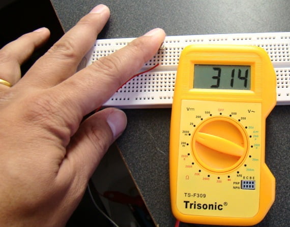
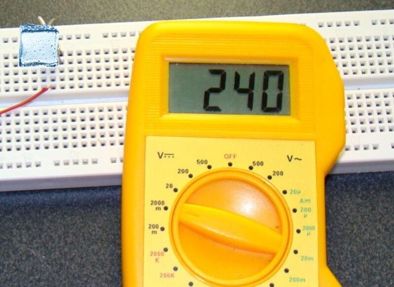
LM35 සෙන්සරය පරීක්ෂා කිරීම
LM35 සෙන්සරය පරීක්ෂා කිරීම ඉතා පහසුය, වම් පින් එක 4V දක්වා 30V අතර බල සැපයුමකට සම්බන්ධ කරන්න (AA බැටරි හතරක් වඩාත් සුදුසු වේ) සහ දකුණු පින් එක GND සමග සම්බන්ධ කරන්න (සංවේදකයේ පැතලි පැත්ත ඔබගේ මුහුණ දෙසට හරවා ගත් විට). දැන් ඔබේ මල්ටිමිටරය DC වෝල්ටීයතා ගණනය කරන ආකාරයට සකස් කර GND සහ මැද PIN එකට සම්බන්ධ කරන්න. එවිට කාමර උෂ්ණත්වයේ දී (25 C), වෝල්ටීයතාව 0.25V පමණ විය යුතුය.
උෂ්ණත්වය ඉහළ යාමක් බලාගැනීමට සංවේදකයේ ප්ලාස්ටික් නඩුව මෘදු ලෙස මිරිකීමට උත්සාහ කරන්න.
නැතහොත් අයිස් කැටයකින් සංවේදකය ස්පර්ශ කිරීමට උත්සාහ කරන්න (ප්ලාස්ටික් බෑගයක, එවිට ඔබේ පරිපථය ජලය සමඟ සම්බන්ධ වී උෂ්ණත්වය පහත වැටීම බලන්න.
LM35 සෙන්සරයේ පින් පවතින ආකාරය
LM35 විවිධ වර්ග තුනකින් යුක්ත වන නමුත් වඩාත් බහුලව දැකගත හැක්කේ 3-පින් To-92 වර්ගය වන අතර එය ට්රාන්සිස්ටරයක් සේ පෙනේ. අපි එහිපින් පවතින ආකාරය බලමු.

පරිපථ සැකැස්ම
ආර්ඩුයිනෝ බෝර්ඩ් එකකට LM35 සෙන්සරයක් පහසුවෙන් සම්බන්ධ කර ගත හැකිය ඔබට අවශ්ය වන්නේ ජම්පර් වයර් 3ක් පමණයි.
සංවේදකය 5v සිට බල ගැන්විය හැකිය. Vcc එසේත් නැත්නම් ධන වෝල්ටීයතාව + එදිරිව හා ඍණ GND සම්බන්ධ වේ. මැද පින් එක යනු සංවේදකයේ ඇනලොග් සිග්නල් නිකුත් කරන පින් එක වන අතර එය ආර්ඩුයිනෝ හි A0 ඇනලොග් ආදානය වෙත සම්බන්ධ වේ.
LM35 සමඟ අත්හදා බැලීම් සදහා පහත පරිපථ සටහන භාවිතා කරන්න :
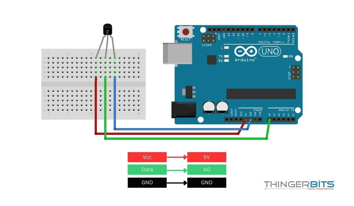
වායු උෂ්ණත්වය මැනීම සඳහා සංවේදකය විවෘත වාතයේ තබන්න එසේ නොමැති නම් රීට් සින්ක් එකක්ක සම්බන්ධ කරන්න
ඇනලොග් සිග්නල් මගින් උෂ්ණත්ව දත්ත කියවීම
ඉහත පරිපථ සටහන තුළ, LM35 හි ප්රතිදාන පින් එක Arduino බෝර්ඩ් එකෙහි ඇනලොග් පින් වලින් එකකට සම්බන්ධ වේ. ඔබට එය A0 සිට A5 ඕනෑම පින් එකකට සම්බන්ධ කල හැකිය. එම පින් එක වෙත ලැබෙන අගය analogRead() ෆන්ෂන් එක මගින් කියවිය හැකිය.
කෙසේ වෙතත්,analogRead() ෆන්ෂන් එක මගින් සෙන්සර් එකෙන් ලබාදෙන වෝල්ටීයතාව කෙලින්ම ලබා නොදේ. ඒ වෙනුවට එය ආදාන(ඉන්පුට්) වෝල්ටීයතාවය 0 සහ 5V (තාක්ෂණිකව එය මෙහෙයුම් වෝල්ටීයතා I. 5V හෝ 3.3V වේ) අතර ADC ලෙස සකස් කර ගත යුතුය. ඔබ මෙහෙයුම් වෝල්ටීයතා වෙනස් නොකරන්නේ නම් ඇනලොග් දත්ත කියවීම් පරාසය 0 සිට 1023 දක්වා පරතරය අතර අගයක් ලැබෙන බැවින්. පහත සුත්රය භාවිතා කර ඔබට ප්රතිදාන වෝල්ටීයතා අගය ලබා ගත හැකිය
Vout = (reading from ADC) * (5 / 1024)
මෙම සුත්රය මගින් ADC වෙතින් 0-1023 ලෙස ලබා දෙන අගය 0-5V බවට පරිවර්තනය කරයි
ඉන්පසු ලැබෙන වෝල්ටීයතා අගය උෂ්ණත්වය බවට පරිවර්තනය කිරීම සඳහා පහත සුත්රය භාවිතා කරන්න:
Temperature (°C) = Vout * 100
Sketch 1.1
ඔබගේ අත්හදාබැලීම් හා වියපෘති සදහා LM35 උෂ්ණත්වය සංවේදකය දත්ත නිවැරදිව ලබා ගන්නා ආකාරය පහත දැක්වේ.
පහත කෝඩ් එක ආර්ඩුයිනෝ බෝර්ඩ් එක වෙත අප්ලෝඩ් කරන්න එවිට ඇනලොග් පින් A0 භාවිතා කරමින් LM35 වෙතින් ලබා ගන්නා අගය කියවන අතර, serial මොනිටරයේ එම දත්ත වලට අනුකුල උෂ්ණත්වය (° C සහ ° F යන දෙකෙන්ම පෙන්නුම් කරයි.
// Define the analog pin, the LM35's Vout pin is connected to
#define sensorPin A0

void setup() {
  // Begin serial communication at 9600 baud rate
  Serial.begin(9600);
}

void loop() {
  // Get the voltage reading from the LM35
  int reading = analogRead(sensorPin);

  // Convert that reading into voltage
  float voltage = reading * (5.0 / 1024.0);

  // Convert the voltage into the temperature in Celsius
  float temperatureC = voltage * 100;

  // Print the temperature in Celsius
  Serial.print("Temperature: ");
  Serial.print(temperatureC);
  Serial.print("xC2xB0"); // shows degree symbol
  Serial.print("C  |  ");

  // Print the temperature in Fahrenheit
  float temperatureF = (temperatureC * 9.0 / 5.0) + 32.0;
  Serial.print(temperatureF);
  Serial.print("xC2xB0"); // shows degree symbol
  Serial.println("F");

  delay(1000); // wait a second between readings
}
ඔබට දැන් serial මොනිටරයේ පහත දැක්වෙන ආකාරයට අගයන් දැකිය හැකිය.
Code Explanation:
කෝඩ් එක ආරම්භ වන්නේ LM35 සෙන්සරයේ පින් එක සම්බන්ධ කර ඇති ආර්ඩුයිනෝ පින් එක අර්ථ දැක්වීමෙනි.එය පහත ආකාරයට සිදු කරයි
#define sensorPin A0
setup() ෆන්ෂන් එක තුළ, අපි පරිගණකය සමඟ ඇති serial සම්බන්ධතාවයට අදාලව සැකසුම් ලබාදෙන්නෙමු
void setup() {
Serial.begin(9600);
}
loop() ෆන්ෂන් එක තුළ , අපි ප්රථම වරට LM35 සිට analogRead()ෆන්ෂන් එක භාවිතා කරමින් ඇනලොග් signal හරහා ලැබෙන දත්ත ලබා ගන්නෙමු .
int reading = analogRead(sensorPin);
ඊළඟට, ඇනලොග් මගින් ලැබෙන දත්ත වෝල්ටීයතාව බවටත්, පසුව උෂ්ණත්වය බවටත් සදහා කලින් යොදා ගත් සුත්ර භාවිතා කරන්නෙමු.
float voltage = reading * (5.0 / 1024.0);
float temperatureC = voltage * 100;
ඊළගට එම ලැබෙන අගයන් serial මොනිටරයේ බලා ගැනීම සදහා කේත සකස් කරමු
Serial.print("Temperature: ");
Serial.print(temperatureC);
Serial.print("\xC2\xB0"); // shows degree symbol
Serial.print("C  |  ");
අපට ලැබෙන උෂ්ණත්වය අගය සෙල්සියස් (° C) ලෙස ඇත. එය සරල සුත්රයක් භාවිතයෙන් ෆැරන්හයිට් (° F) වෙත පරිවර්තනය කර serial මොනිටරයේ පෙනෙන ලෙස සකස් කර ඇත.
T(°F) = T(°C) × 9/5 + 32
float temperatureF = (temperatureC * 9.0 / 5.0) + 32.0;
Serial.print(temperatureF);
Serial.print("\xC2\xB0"); // shows degree symbol
Serial.println("F");
Automatic Fan Control System
මෙම ව්යාපෘතියේදී LM35 උෂ්ණත්ව සංවේදකය මගින් ලැබෙන අගයන් ගණනය කර ඒ ඔස්සේ fan එකක් එසේ නැත්නම් DC මෝටර් එකක් ON OFF කිරීම සදහා ප්රෝග්රෑම් එකක් සකස් කරමු
අවශ්යය උපාංග
[gap height=”25px”]
[ux_products style=”vertical” type=”row” columns=”2″ depth=”1″ depth_hover=”2″ show_quick_view=”0″ equalize_box=”true” ids=”423,4125,4134,4143,6277″ image_width=”42″ image_hover=”grayscale” text_pos=”middle” text_align=”left”]
උපාංග පිලිබද දැනුම
3V DC Toy Motor
මෙම ව්යාපෘතියට අවශ්ය වන DC මෝටර් එකක් වැඩ කරන ආකාරය මුලිම අධ්යනය කරමු. ලෝකයේ විවිධ ඉලෙක්ට්රොනික් මෙවලම් හා උපකරණ වල බහුලව භාවිතා වන ඉලෙක්ට්රොනික් මෝටර් ලෙස DC මෝටර් හැදින්විය හැකිය. සෑම විදුලි මෝටරයක් මෙන්, විද්යුත් ශක්තිය යාන්ත්රික ශක්තිය බවට පරිවර්තනය කර විවිධ කාර්යන් සිදු කරගැනීමට මෝටර් භාවිතා කරයි . කෙසේ වෙතත්, DC මෝටර්ස් වෙනත් විදුලි මෝටර වලින් වෙනස් වෙනස් වන්නේ මෙයට බල සැපයුම ලෙස DC විද්යුත් ධාරාවක් ලබා දිය යුතුය.
But how exactly do DC motors convert DC electrical energy into shaft rotation? To find the answer to this question, engineers must first understand some fundamental concepts like the Lorentz law and Fleming’s left-hand rule.
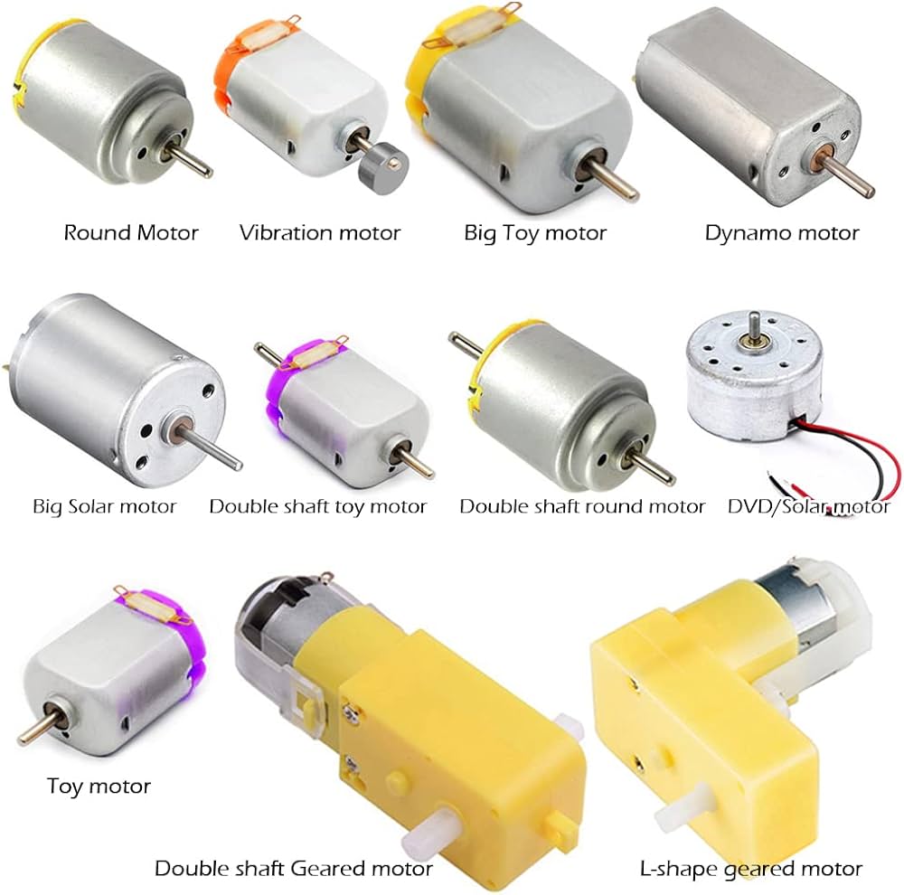
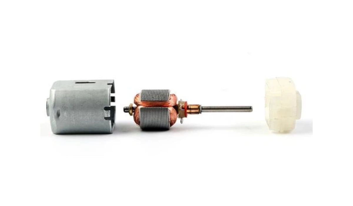
Figure 1: DC motors are powered by direct current sources, such as batteries and DC power supplies
Understanding the Lorentz force law
Imagine a length of ordinary wire is rolled into a big loop and placed between the poles of a powerful horseshoe magnet. If the ends of this wire are connected to a battery, the wire will jump up suddenly. Lorents force law explains why this amazing phenomenon happens.
Lorentz law explains that a current-carrying conductor experiences a force when placed in a magnetic field. When electric current flows through a conductor, it creates a magnetic field around the conductor. This temporary magnetic field interacts with a permanent magnet’s field, attracting (or repelling) the magnetism. As a result, the wire experiences a force that causes it to jump.
The direction of this force (or motion of the conductor) can be obtained using Fleming’s left-hand rule.
Fleming’s left-hand rule
The Flemming’s rule was developed by John Ambrose Fleming in the 19th century. It is a visual mnemonic that uses the left hand’s thumb, index, and middle fingers to determine a conductor’s direction of motion in a magnetic field.
For example, consider a situation where the thumb, index finger, and middle finger are held out so that all three are at right angles, as shown below. Fleming’s rule states that if the middle finger points in the current direction and the index finger points in the magnetic field direction, the thumb points in the direction of the conductor’s thrust.

And the magnitude of this force can be calculated using:
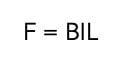
Where:
B = magnetic flux density of the field (measured in Tesla or T)
I = current on the conductor (A)
L = length of the conductor in the field (m)
However, keep in mind that the current direction is from the battery’s positive terminal to the negative terminal, while the magnetic field flows from the magnet’s north pole to the south pole.
Fleming’s rule and the working principle of DC motors
Figure 3 shows the interior of a typical DC motor. It comprises two essential parts: the stator (or the stationary part of the motor) and the rotor (or rotating part of the motor). A DC motor’s stator is usually a ring of permanent magnets. In contrast, the rotor is wrapped several times with a wire and nested into the stator.
Figure 2: Fleming’s left-hand rule
And the magnitude of this force can be calculated using:
Where:
B = magnetic flux density of the field (measured in Tesla or T)
I = current on the conductor (A)
L = length of the conductor in the field (m)
However, keep in mind that the current direction is from the battery’s positive terminal to the negative terminal, while the magnetic field flows from the magnet’s north pole to the south pole.
Fleming’s rule and the working principle of DC motors
Figure 3 shows the interior of a typical DC motor. It comprises two essential parts: the stator (or the stationary part of the motor) and the rotor (or rotating part of the motor). A DC motor’s stator is usually a ring of permanent magnets. In contrast, the rotor is wrapped several times with a wire and nested into the stator.
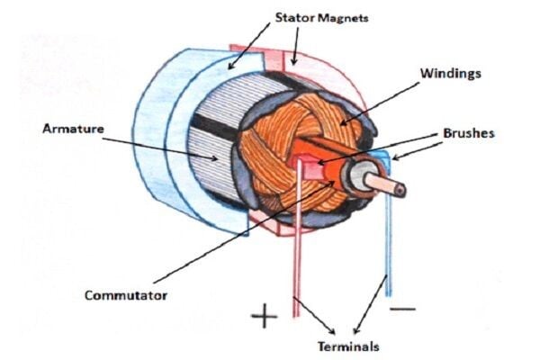
Figure 2: DC motor parts
Now when direct current starts flowing through the rotor windings, it causes a magnetic field to be generated around the winding. This magnetic field interacts with the stator’s magnetic field, causing a force to be generated in a direction given by Fleming’s left-hand rule. Because of the way the stator is constructed, this force is manifested as the rotation of the rotor.
Back EMF of DC motors and motor speed
The fundamental laws of energy conservation explain that it is impossible to achieve energy conversion unless there is some form of opposition. In the case of DC motors, this opposition is provided by the back EMF.
Back EMF is the electromotive force that opposes the applied voltage. It is induced in the conductor when the motor’s armature is rotating and cutting across magnetic field lines. The magnitude of back EMF is directly proportional to the speed of the motor, according to the equation below:
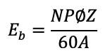
Where:
N = motor speed
P = number of poles
A = number of parallel parts through the armature
Z = total number of conductors in the armature
fi = Flux per pole
Choosing between the different types of DC motors
There are several types of DC motors, all of which have similar modes of operation but differ in design, efficiency, and capability. For instance, permanent DC motors and series DC motors are among the most commonly used DC motors for many applications today.
පරිපථ සැකැස්ම
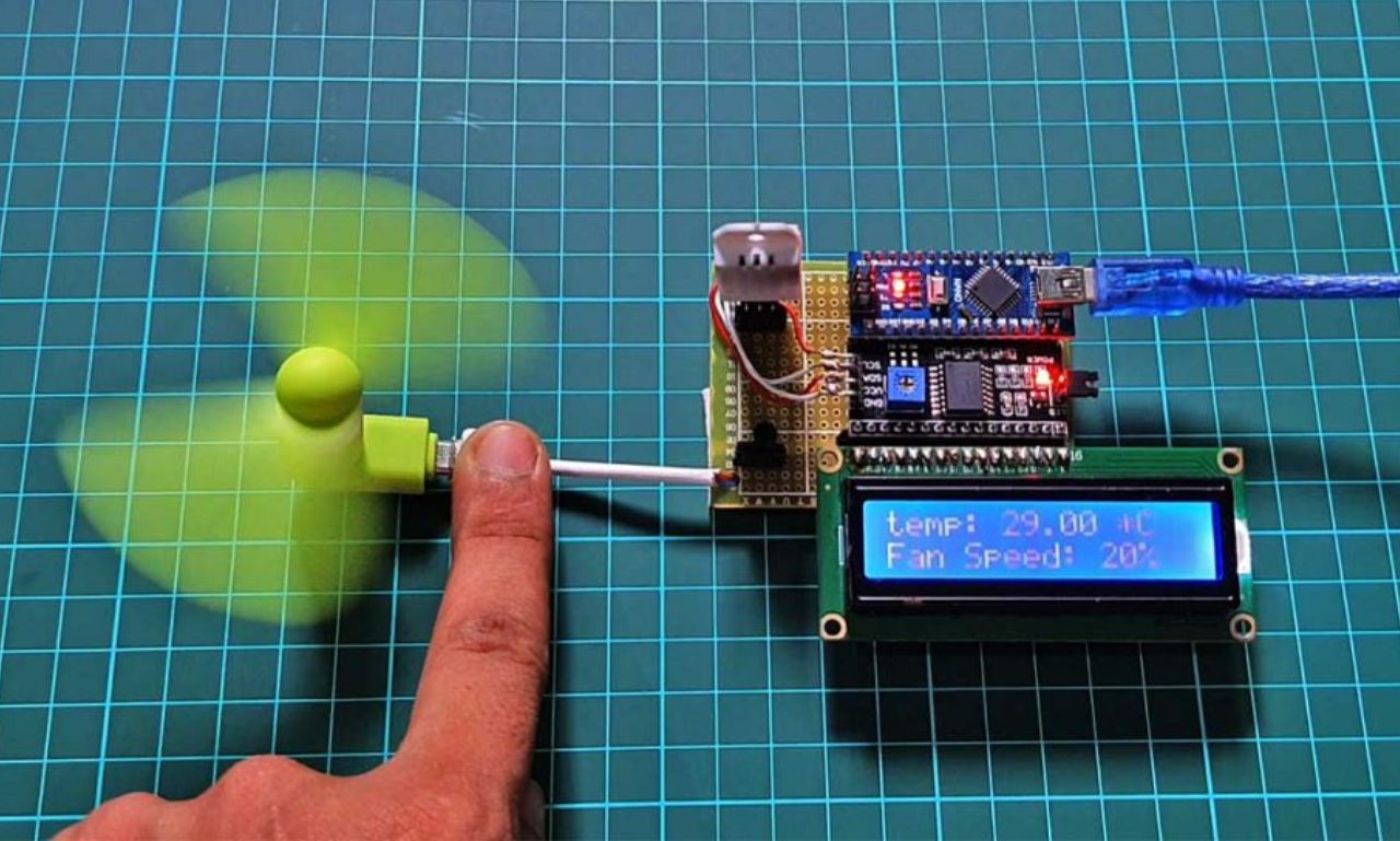
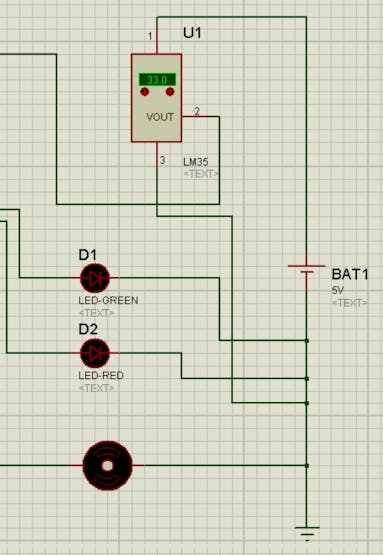
This project is all about making an automatic fan control system with automatically switch on and off the fan according the temperature inside the room. Here I have used a microcontroller Arduino UNO you can use MINI also but there will be some power regulations problem will occur so go for UNO 🙂 The temperature sensor here is the LM35 you can use module also it will give you the more accurate readings. There are 2 LEDs which indicates status of the fan Green- ON, Red- OFF. There is one DC motor which is our fan, we are going to control this motor.
Sketch 1.2
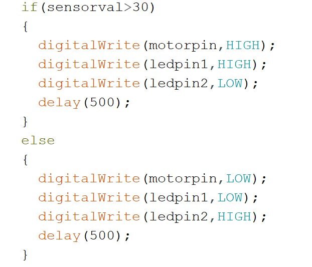
As LM35 is an analog sensor we have to use AnalogRead() operation to get the values from the sensor and then we will perform function using if-else loop. If the temperature is greater then 30 then Green light will ON and motor(fan) stars rotating to maintain the room temperature. else the fan will be in OFF condition and Red led will remain on.
I have made the circuit in the Proteus software and transfer the.HEX into the Arduino, If you have the hardware you can directly make circuit using it. In Arduino Ide you can see the result using serial monitor and in Proteus also you can have serial monitor in the instrument option which will show you the values.
